# Hardware
# Prebuilt
There are some prebuild matrixes, which you can buy and replace the stock firmware with PixelIt.
| Quantity | Name | Link | Notice |
|---|---|---|---|
| 1 | Ulanzi TC001 Pixel Clock | Offical Store (opens new window) | ESP32, 8x32 pixel matrix, three buttons, build in battery and brightness sensor. The buildin in buzzer is not supported at the moment. |
# DIY components list
If you want to build your own PixelIt, you can find the components here. You need a soldering iron and some soldering skills. If you don't have any experience with soldering, you can find some tutorials on the internet. It is also recommended to use a soldering iron with temperature control. This makes it easier to solder the components without damaging them. At minimum, you need
- a Matrix which fits your needs
- a Microcontroller (MCU)
- a 1000uF capacitor
- a power supply
You can extend your PixelIt with some sensors and buttons. You can find some examples below.
Disclaimer
The drawing are only examples. Check the pinout of your microcontroller before soldering.
# Matrix
Choose a matrix which fits your needs. At the moment the project is optimized for the resultion of 8x32 pixels. Yes, you also could use four 8x8 tiles. And yes, you also could use other sizes, but you have to change the firmware to use it. Don't forget the 1000uF capacitor. It prevents a initial onrush of current from damaging the pixels. It also provides a small power reservoir for abrupt changes in brightness that the power source might not otherwise handle. Otherwise it can happen that the microcontroller restarts or it comes to gliches in the matrix.
| Quantity | Name | Link | Notice |
|---|---|---|---|
| 1 | WS2812B LED Matrix 8x32 | Amazon (opens new window) AliExpress (opens new window) | |
| 4 | WS2812B LED Matrix CJMCU 8x8 | Amazon (opens new window) AliExpress (opens new window) | alternative |
| 4 | MicroMatrix by foorschtbar 8x8 | GitHub (opens new window) | alternative (really micro) |
| 1 | Capacitor 1000uF/6.3V or higher | Amazon (opens new window) AliExpress (opens new window) |
# Microcontrollers
You can use a ESP8266 or a ESP32 based microcontroller. The ESP32 is a bit faster and has more memory. The ESP8266 is a bit cheaper. We recommend the Wemos D1 Mini (ESP8266) because we not use or plan to use the additional features of the ESP32. But you can use the ESP32 if you want.
| Quantity | Name | Link | Notice |
|---|---|---|---|
| 1 | Wemos D1 Mini V3 (ESP8266) | Amazon (opens new window) AliExpress (opens new window) | |
| 1 | Wemos D1 ESP32 (ESP32) | Amazon (opens new window) AliExpress (opens new window) | alternative |
# Extensions
- LDR GL5516 Sensor (Brightness)
- DHT22 Sensor (Temperature & Humidity
- BME280 Sensor (Temperature, Humidity & Pressure)
- BME680 Sensor (Temperature, Humidity, Pressure & Gas)
- DFPlayer Mini (MP3 Player, Soundeffects)
- Touch Buttons (Touch Sensor)
# Wiring guide
Only the Matrix PIN is fixed. You can choose the PIN for the other components in the WebUI. Please keep in mind that some pins are used by the microcontroller itself, had defined values at boot or aren't allow to had a defined value at boot and so on. So you can't use all pins for all components.
Here you can find a good overview of the pins of the ESP8266 and ESP32:
# Basic wiring
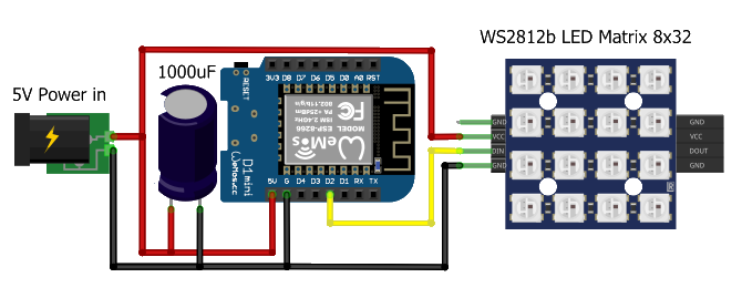
| ESP8266 | ESP32 | Matrix | Function | Note |
|---|---|---|---|---|
| 5V | VIN | VCC | Power supply (+) | |
| G | GND | GND | Power supply (-) | |
| D2 | GPIO27 | DIN | Data In |
TIP
If you reduce the brightness of the matrix, powering everything via USB should be sufficient for testing. However, it is recommended to use a high-quality power supply for normal operation. A 20W (5V/4A) power supply is sufficient for this.
TIP
The 1000uF capacitor prevents the initial onrush of current from damaging the pixels. It also provides a small power reservoir for abrupt changes in brightness that the power source might not otherwise handle. Otherwise it can happen that the microcontroller restarts or it comes to gliches in the matrix.
# LDR GL5516
Enables automatic brightness control and exposes the brightness/lux value via API and MQTT.
# Components
| Quantity | Name | Link |
|---|---|---|
| 1 | LDR GL5516 | Amazon (opens new window) AliExpress (opens new window) |
| 1 | Resistor 10k Ohm | Amazon (opens new window) AliExpress (opens new window) |
# Wiring
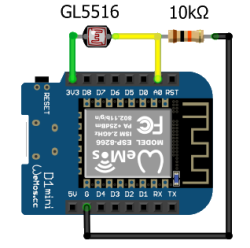
| ESP8266 | ESP32 | LDR GL5516 | Resistor 10k Ohm | Function | Note |
|---|---|---|---|---|---|
| 3V3 | 3V3 | Leg 1 | |||
| G | GND | - | Leg 1 | ||
| A0 | GPIO34 | Leg 2 | Leg 2 | Acts as a voltage divider |
# DHT22 Sensor
Exposes temperature and humidity values via API and MQTT.
# Components
| Quantity | Name | Link |
|---|---|---|
| 1 | DHT22 | Amazon (opens new window) AliExpress (opens new window) |
| 1 | Resistor 4.7k Ohm | Amazon (opens new window) AliExpress (opens new window) |
# Wiring
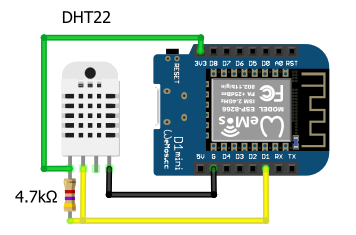
| ESP8266 | ESP32 | DHT22 | Function | Note |
|---|---|---|---|---|
| 3V3 | 3V3 | VCC | Power supply (+) | |
| G | GND | GND | Power supply (-) | |
| D1 | GPIO17 | DATA |
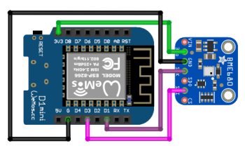
# BME280 Sensor
Exposes temperature, humidity and pressure values via API and MQTT.
# Components
| Quantity | Name | Link |
|---|---|---|
| 1 | BME280 3.3V | Amazon (opens new window) AliExpress (opens new window) |
# Wiring
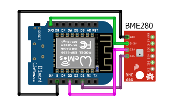
| ESP8266 | ESP32 | BME280 | Function | Note |
|---|---|---|---|---|
| 3V3 | 3V3 | VCC | Power supply (+) | |
| G | GND | GND | Power supply (-) | |
| D1 | GPIO18 | SCL | Clock | |
| D3 | GPIO19 | SDA | Data |
# BME680 Sensor
Exposes temperature, humidity, pressure and gas values via API and MQTT.
# Components
| Quantity | Name | Link |
|---|---|---|
| 1 | BME680 | Amazon (opens new window) AliExpress (opens new window) |
# Wiring
| ESP8266 | ESP32 | BME680 | Function | Note |
|---|---|---|---|---|
| 3V3 | 3V3 | VCC | Power supply (+) | |
| G | GND | GND | Power supply (-) | |
| D1 | GPIO18 | SCL | Clock | |
| D3 | GPIO19 | SDA | Data |
# DFPlayer Mini
With the DFPlayer Mini you can play sound files. The sound files must be stored on the micro SD card on the the DFPlayer Mini. It has a built-in amplifier and can therefore be connected directly to a speaker. You could set a file to play when the PixelIt starts up, or you could set a file to play when a button is pressed. All files could also played via API or MQTT.
# Components
| Quantity | Name | Link |
|---|---|---|
| 1 | DFPlayer Mini MP3 Player | Amazon (opens new window) AliExpress (opens new window) |
# Wiring
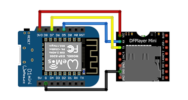
| ESP8266 | ESP32 | DFPlayer Mini | Function | Note |
|---|---|---|---|---|
| 3V3 | 3V3 | VCC | Power supply (+) | |
| G | GND | GND | Power supply (-) | |
| D5 | GPIO20 | RX | PixelIt TX -> DFPlayer RX | |
| D7 | GPIO21 | TX | PixelIt RX <- DFPlayer TX |
# Touch Buttons
With the touch sensors you can control the PixelIt. You can use the touch sensors to switch trigger MQTT messages or some basic stuff like toogle the matrix on/off or control the MP3 player.
# Components
| Quantity | Name | Link |
|---|---|---|
| 1 | TTP223 Touch Sensor | Amazon (opens new window) AliExpress (opens new window) |
# Wiring
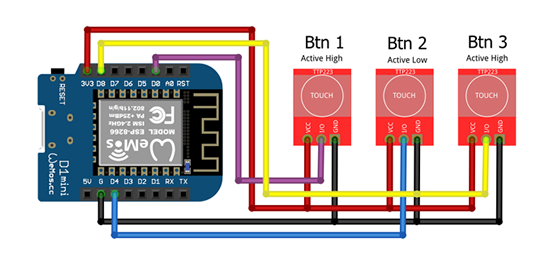
| ESP8266 | ESP32 | Button left | Button middle | Button right | Function | Note |
|---|---|---|---|---|---|---|
| 3V3 | 3V3 | VCC | VCC | VCC | Power supply (+) | |
| G | GND | GND | GND | GND | Power supply (-) | |
| D0 | GPIO22 | I/O | - | - | Touch signal | See disclaimer |
| D4 | GPIO23 | - | I/O | - | Touch signal | See disclaimer |
| D8 | GPIO24 | - | - | I/O | Touch signal | See disclaimer |
Disclaimer PIN D4 on ESP8266 (Wemos D1 Mini)
The touch sensors have two solder bridges on the board which can be connected. This allows switching between active high (when pressing high) and active low (when pressing low). When you use D4, is absolutely necessary, otherwise the wemos will not start. To prevent this, bridge A of the middle touch sensor must be closed. This sets the I/O pin to active low. Other touch sensors are not recommended, because they have no possibility to be set to active low.
TTP223 Image for Fritzing by rbricheno (opens new window).
# 3D Printing Files
 by PlastikJunkies
# Downloads
# Makes
Make sure to check out this discussion page for some inspiration.
# Troubleshooting
See Troubleshooting.
← Introduction Firmware →